Overview
The internals of a circuit are fully encapsulated and therefore in order to invoke its behavior, it must expose a public interface to the outside world. This interface consists of:
- Pin definitions - named connection points that expose designated faces to external connectors
- Prototypes - specifications that constrain the circuitry that can be attached at the designated points
Exposing Connection Points
The process of exposing an internal object consists of the following steps:
- Create a definition pin that will reference the object. This is done by dragging the appropriate definition pin from the toolbox (Definitions) onto the circuit. If a consumer face is being exposed then you will require a Definition Consumer Pin otherwise you will require a Definition Provider Pin. The pin will snap to the nearest side (left or right). By convention, circuit inputs generally appear on the left and outputs appear on the right.
- Create a reference connection from the definition pin to the face of the object that you wish to expose (see Connecting Circuit Objects). The pin type is an extension of the object face type, hence a provider pin is connected to a Provider face etc.
- Rename the definition pin with a name that meaningfully describes what it is referencing (e.g. the object name, the data store type, the active object function or its function within the circuit). Names like Input/Output are not recommended. Their meaning may be clear when looking at the definition, but when looking at its instance an Input pin may be requiring input or providing input.
Defining the Prototype
There are two alternative methods of creating a prototype:
- Manual placement
- Automatic generation
These mechanisms are both described in detail below:
Manual Placement
- Drag a Prototype object from the toolbox (Definitions) and place it on the circuit page. This will create a blue box with rounded corners, which is the container for subscriptions and publications.
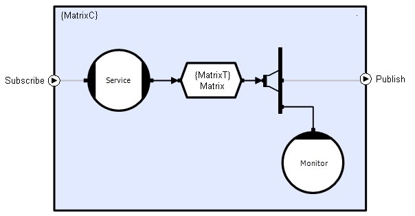
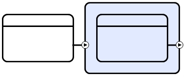
- Drag a Publication or Subscription prototype from the toolbox (Definitions) and place it on - or to the side of - the blue prototype box. Subscription prototypes appear outside the blue box, whereas publication prototypes appear within. The subscription or publication will attach to the left or right side of the box depending on where it is dropped relative to the center of the blue box:
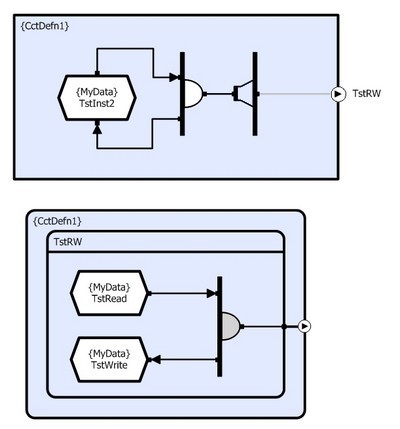
- In order to create a valid publication prototype you must reproduce the circuitry to which the prototype is attached in tree form (connections to the same provider are drawn as connections to separate provider objects) as far back as the ultimate provider objects (stores and semaphores), excluding transparent objects. The prototype will be automatically resized and laid out when connections are made, so build the mini-circuit from the pin back to the ultimate providers. All connections should be made using the Event Connection tool. The example below shows a circuit with a transparent distributor and a repeated connection to a data store:

Creating a subscription prototype is the fundamentally the same. However, rather than describing circuitry exposed by this definition, the prototype contains circuitry that must be provided by an external connector.
Automatic Generation
Publication prototypes contain a subset of the information already specified in the circuit definition and as a result they can be generated automatically by simply selecting the appropriate pin and then selecting the Generate Prototype command from the right-click context menu.
Unfortunately, subscription prototypes require details of another circuit and so they cannot be simply auto-generated in the same way. However, a corresponding publication often exists that contains the required prototype circuitry. This means that the Cut/Copy/Paste functionality can be used copy all of the objects from the existing publication prototype into the subscription prototype. This is achieved by:
- Selecting all the objects within the prototype to copy from
- Selecting Edit | Copy or clicking the Copy button on the toolbar or pressing <Ctrl>+C
- Selecting the target subscription prototype
- Selecting Edit | Paste or clicking the Paste button on the toolbar or pressing <Ctrl>+V
Mandatory/Optional Pins
Some circuits do not work or are meaningless if some of their pins are not connected. In others a pin may have been provided to allow for extensibility.
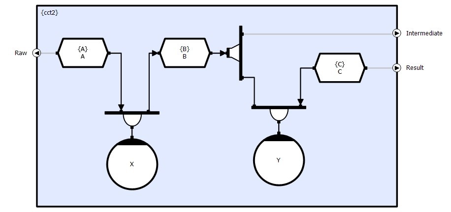
In the example below, the circuit receives raw input data (A) and generates a result (C). However, it also provides access to the intermediate data (B). Pins Raw and Result are mandatory, but pin Intermediate is optional.

Mandatory (default) Pins are shown in Black whilst Optional Pins are shown in Grey.

